GB/T 32833-2016/隔热耐火砖抗剥落性试验方法/Determination of spalling resistance of insulating fire bricks
隔热耐火砖抗剥落性试验方法
1范围
本标准规定了隔热耐火砖抗剥落性试验方法的术语和定义、原理、仪器设备、试样、试验步骤、结果计算及处理和试验报告。
本标准适用于隔热耐火砖抗剥落性的测定。
2规范性引用文件
下列文件对于本文件的应用是必不可少的。凡是注日期的引用文件,仅注日期的版本适用于本文件。凡是不注日期的引用文件,其最新版本(包括所有的修改单)适用于本文件。
GB/T 8170 数值修约规则与极限数值的表示和判定
GB/T 16839.1 热电偶 第1部分:分度表
GB/T 16839.2 热电偶 第2部分:允差
GB/T 18930 耐火材料术语
3术语和定义
GB/T 18930 界定的术语和定义适用于本文件。
4 原理
在规定的试验温度和一定压力的空气为冷却介质的条件下,一定形状和尺寸的试样在经受急热急冷温度突变后,通过试验前后试样的质量损失率来确定隔热耐火砖的抗剥落性,
5仪器设备
5.1嵌板装置
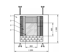
主要由测试样砖、保护砖、隔热材料、嵌板框架组成。嵌板装置具体的结构轮见图 1。
5.2加热装置
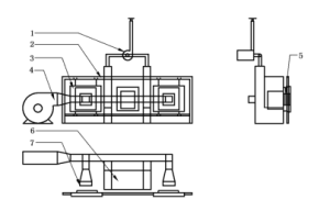
加热装置用于试验样品的加热和抗剥落性试验。加热装置内温度应能够达到1400℃,炉温用热电偶测量,加热过程采用自动化控制,温差不超过±10℃。在移动嵌板装置过程中,加热装置内温降不超过 30 ℃ ,并于5 min 内能恢复到规定温度。具体的结构轮廓见图 2。

说明:
1–嵌板框架;
2–隔热材料;
3–保护砖;
4–测试样砖。
图1嵌板装置

说明:
1–排烟风机;
2–嵌板吊架;
3–嵌板装置;
4–鼓风机;
5–测试样砖;
6–加热炉膛;
7–出风口。
图2 加热装置结构图
5.3 温度测量装置
采用能适用于试验温度的热电偶(见 GB/T 16839.1 或 GB/T 16839.2),温度控制仪用于控制升温速率。
5.4 急冷装置
5.4.1 鼓风机
作用是将规定压力的清洁、干燥空气提供给送风系统,
5.4.2 送风系统
将来自鼓风机的冷空气通过风道送至试样急冷区域。出风口为460 mmX460 mm 的方口,出风口距离测试样砖 250 mm,风速为(10±0.5)m/s。
5.5 转移装置
用于滑动嵌板装置。
5.6电热鼓风干燥箱
使用温度范围为0℃~300 ℃。
5.7天平
分度值为 0.1 g。
6 试样
6.1 试样尺寸
采用 230 mmX114 mmX65(75)mm 的直形砖试样。当砖型较大时,可以在大砖上切取符合上述尺寸要求的试样,每块制品上只能切取一个试样。
6试样
6.1 试样尺寸
采用 230 mmX114 mmX65(75)mm 的直形砖试样。当砖型较大时,可以在大砖上切取符合上述尺寸要求的试样,每块制品上只能切取一个试样。
6.2 试样数量
试样数量为14块(230 mmX114 mmX65 mm)或 12块(230 mmX114 mmX75 mm),
7 试验步骤
7.1 试样干燥
试样在(110士5)℃下干燥至恒量,干燥后的试样不得再次受潮。
7.2 砖墙码砌
7.2.1 称量每块试样的质量 m0,精确到1g,并在每块试样测试面为 230 mmX65(75 mm)的面上做好标记编号。
7.2.2 将试样干码砌成面积为 460 mmX460 mm的砖墙作为测试样砖,测试样砖的测试面应拍照存档。
7.2.3 测试样砖的四周采用合适等级的保护砖,其他部分采用满足使用条件的隔热材料。
7.2.4 采用合适等级的保护砖码砌成砖墙作为保护墙,用于加热装置升温过程以及测试样砖移开急冷时,封堵加热装置炉口。
7.3 砖墙急热过程
在加热装置升温过程中,由保护墙封堵住炉口。试验温度应比测试砖实际最高使用温度低 10℃~40 ℃或协商确定。以最快升温速率将炉温升至试验温度并保温 10 min,随后移开保护墙,将测试样砖迅速移至加热装置炉口,在该温度下保持 10 min。
7.4 砖墙急冷过程
7.4.1 将在试验温度下保温 10 min 后的测试样砖,迅速移至冷却装置前以(10士0.5)m/s的风速吹风急冷 10 min,然后再移至加热装置炉口,急热 10 min。测试样砖重复该急热急冷过程,直至达到 10 次循环。
7.4.2 10次急热急冷循环结束后,关闭加热装置,用保护墙封堵炉口,将测试样砖在室温下自然冷却。
7.5 砖墙拆解
冷却后,将测试样砖的测试面拍照存档,之后小心地拆解砖墙,注意保持试样完整,避免破坏。将拆解后的试样按原码砌位置堆放,拆解中的试样剥落部分装袋,再次拍照存档。
7.6 试样的测量
将试样烘干至恒量后,再次称量每块试样的质量 m,,精确至1g,记录数值,
8 结果计算及处理
试样抗剥落性用质量损失率表示,按式(1)计算试样的平均质量损失率,计算结果精确到小数点后-位,按 GB/T 8170 进行处理。
![]()
式中:
P–试样的平均质量损失率,%;
m0–试验前试样的总质量,单位为克(g);
m1–试验后试样的总质量,单位为克(g)。
9试验报告
试验报告应包括:
a)委托单位名称;
b)试样名称及牌号;
c)试验条件;
d)试样数量和尺寸;
e)试样的平均质量损失率;
f)试验前后试样对比照片;
g)试验人员及试验日期。
Determination of spalling resistance of insulating fire bricks
1 Range
This standard specifies the terms and definitions, principles, instruments and equipment, samples, test steps, calculation and treatment of results and test reports of the test methods for the anti-spalling property of heat-insulating refractory bricks.
This standard is applicable to the determination of the resistance to spalling of heat-insulating refractory bricks.
2 Normative reference documents
The following documents are essential for the application of this document. For dated references, the date-only version applies to this document. For undated references, the latest version (including all amendment orders) applies to this document.
GB/T 8170 numerical revision rules and limit value representation and judgment
GB/T 16839.1 Thermocouples – Part 1: Index tables
GB/T 16839.2 Thermocouples – Part 2: Tolerance
GB/T 18930 refractory terminology
3 Terms and definitions
The terms and definitions defined in GB/T 18930 apply to this document,
4 Principles
Under the condition that the specified test temperature and the air of a certain pressure are the cooling medium, after the sample of a certain shape and size is subjected to the abrupt heating and cooling temperature change, the mass loss rate of the sample before and after the test is used to determine the spalling resistance of the heat-insulating refractory brick.
5 Instruments and Equipment
5.1 Panel Device
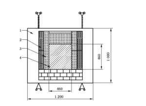
It is mainly composed of test sample brick, protective brick, heat insulation material and panel frame. The specific structural wheel of the panel device is shown in Figure 1.
5.2 Heating Device
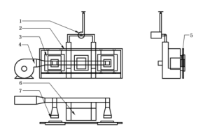
The heating device is used to test the heating and spalling resistance of the test sample. The temperature in the heating device should be able to reach 1400℃, the furnace temperature is measured by thermocouple, the heating process is controlled automatically, and the temperature difference does not exceed ±10℃. In the process of moving the panel device, the internal temperature drop of the heating device does not exceed 30°C, and can be restored to the specified temperature within 5 minutes. The specific structure outline is shown in Figure 2.

Instructions:
1– panel frame;
2– thermal insulation material;
3– protective brick;
4– Test sample brick.
Figure 1 Panel device

Instructions:
1– smoke exhaust fan;
2– panel hanger;
3– panel device;
4– blower;
5– test sample brick;
6– Heating the furnace;
7– Air outlet.
Figure 2 Heating device structure diagram
5.3 Temperature measuring Device
Using a thermocouple suitable for the test temperature (see GB/T 16839.1 or GB/T 16839.2), the temperature controller is used to control the heating rate.
5.4 Quenching Device
5.4.1 Blower
The function is to provide clean and dry air at specified pressure to the air supply system,
5.4.2 Air Supply System
The cold air from the blower is sent to the quench cooling area of the sample through the air duct. The outlet is a square outlet of 460 mmX460 mm, the distance of the outlet from the test sample brick is 250 mm, and the wind speed is (10±0.5)m/s.
5.5 Transfer Device
For sliding panel devices.
5.6 Electric blast drying oven
The operating temperature ranges from 0℃ to 300 ℃.
5.7 Balance
The index value is 0.1g.
6 Sample
6.1 Sample size
Straight brick samples of 230 mmX114 mmX65(75)mm were used. When the brick type is large, the sample that meets the above size requirements can be cut on the large brick, and only one sample can be cut on each product.
6 samples
6.1 Sample size
Straight brick samples of 230 mmX114 mmX65(75)mm were used. When the brick type is large, the sample that meets the above size requirements can be cut on the large brick, and only one sample can be cut on each product.
6.2 Sample Quantity
The sample size is 14 pieces (230 mmX114 mmX65 mm) or 12 pieces (230 mmX114 mmX75 mm),
7 Test Procedure
7.1 Sample Drying
The sample shall be dried to a constant amount at (110 × 5)℃, and shall not be damp again after drying.
7.2 Masonry
7.2.1 Weigh the mass m0 of each sample to 1g and mark and number the surface of each sample with a test surface of 230 mmX65(75 mm).
7.2.2 Brick wall with an area of 460mmX460mm shall be built with the dry code of the sample as the test sample brick, and the test surface of the test sample brick shall be photographed and archived.
7.2.3 Protective bricks of appropriate grade shall be used around the test sample bricks, and the other parts shall be made of thermal insulation materials that meet the operating conditions.
7.2.4 Protective brick codes of appropriate grade shall be used to build brick walls as protective walls, which shall be used to close the furnace of the heating device during the heating process and when the test sample bricks are removed for quenching.
7.3 Rapid heating process of brick wall
During the heating process of the heating device, the furnace opening is blocked by a protective wall. The test temperature should be 10℃~40 ℃ lower than the actual maximum use temperature of the test brick or determined by negotiation. At the fastest heating rate, the furnace temperature was raised to the test temperature and kept warm for 10 min. Then, the protective wall was removed and the test sample brick was quickly moved to the furnace of the heating device and kept at the temperature for 10 min.
7.4 Quenching process of brick wall
7.4.1 The test sample brick that has been held at the test temperature for 10 minutes is quickly moved to the front of the cooling device and cooled for 10 minutes at a wind speed of (10 0.5)m/s, and then moved to the furnace of the heating device for 10 minutes. The rapid heating and cooling process is repeated for the test brick until 10 cycles are reached.
7.4.2 After 10 acute heating and cooling cycles, close the heating device, seal the furnace with a protective wall, and cool the test sample brick naturally at room temperature.
7.5 Disassemble the brick wall
After cooling, the test surface of the test sample brick is photographed and archived, and then the brick wall is carefully disassembled, taking care to keep the sample intact and avoid damage. The disassembled samples are stacked according to the original code building position, the spalling part of the disassembled samples is bagged, and the photos are taken again for archiving.
7.6 Measurement of sample
After drying the sample to a constant amount, weigh the mass m of each sample again, accurately to 1g, and record the value.
8 Result calculation and processing
The spalling resistance of the sample is expressed by the mass loss rate, and the average mass loss rate of the sample is calculated according to formula (1), the calculation result is accurate to the decimal point – place, and the treatment is carried out according to GB/T 8170.
![]()
Formula:
P– the average mass loss rate of the sample,%;
m0- total mass of the sample before the test, in grams (g);
m1- The total mass of the sample after the test, in grams (g).
9 Test Report
The test report shall include:
a) Name of the entrusting unit;
b) Name and grade of the sample;
c) Test conditions;
d) Number and size of samples;
e) The average mass loss rate of the sample;
f) Comparison photos of samples before and after the test;
g) Test personnel and test date.


